How to Re-deploy Your Type 92-A Rack For Service-Level Alarms
Introduction
Through a stroke of good fortune, I came into a full-height Type 92-A rack. It had some old equipment in it which I couldn’t make use of, but there was one intriguing possibility: the alarm panel at the top of the rack. This post in an explanation of how to enable your own alarm panel, should you come into a similarly equiped rack.
The APDP
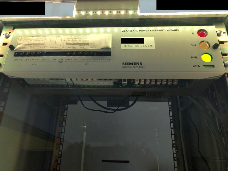
This particular ‘alarm panel’ is called an Alarm & Power and Distribution Panel in the telecommunications industry, and is typically the power conduit to the equipment below. Usually it will provide many amps at -48VDC, and incorporate breakers for each item it powers. It also receives alarm signalling information, and can be used to display an Urgent, Non-Urgen, Normal, and Alarm Receiving Attention (ARA) status via the LED panel. My goal was to repurpose these LEDs for my own use, keeping the housing and 1990s feel intact.
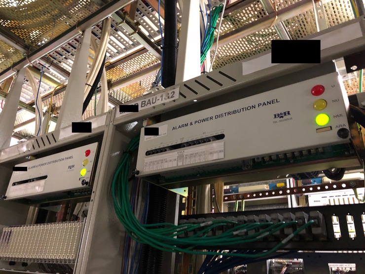
Two racks with APDPs in place, both showing NML (normal) operational status
Working Status
Fortunately the LEDs were integrated into their own (breadboard-spaced!) PCB and pin package. However I was quickly disappointed, as I wasn’t able to light any of the LEDs but the ARA with a 9V battery. I feared they were dead on arrival.
Yet when I managed to borrow other PCBs to test my hypothesis, I found that I needed more than 9V to turn any of them on. I bought a variable power supply, finding that the turn-on voltages for the LEDs was at least 12V (15V for the green LED).
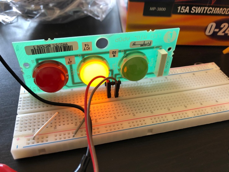
Working LED lights with power supply (not pictured: the resistor I should be using in series)
The Goal
Now, my goal became clear: I wanted to show network/server status on the APDP LED panel. For this, I decided I would need:
- An Arduino with ethernet capabilities (PoE is a bonus, as we only need one cable)
- A server to serve up the current status for the Arduino to show
- A breadboard with components to allow the Arduino to switch the LEDs on and off
I ended up with:
- An Arduino Ethernet with PoE (sadly hard to come by lately, but great for minimising the number of cables you need to run)
- My Synology’s Web Station, and cron to check the network status (see:
ping.shandstatus.phpin the next section) - Wiring up a BJT and some resistors for each LED, and hooking this up to a ~20VDC power supply.
The Code
This code ping.sh is run on my synology, every 10 seconds. It sends one ping, only to a number of important hosts, to ascertain levels of network connectivity.
#!/bin/bash
DIR='/volume1/web/arduino'

touch ${DIR}/ping.txt

ping -q -c 1 192.168.2.98 2>&1 > /dev/null
if [ $? -eq 0 ]; then
    touch ${DIR}/joel.txt
fi

ping -q -c 1 google.com 2>&1 > /dev/null
if [ $? -eq 0 ]; then
    touch ${DIR}/dns.txt
else
    rm ${DIR}/dns.txt
fi

ping -q -c 1 8.8.8.8 2>&1 > /dev/null
if [ $? -eq 0 ]; then
    touch ${DIR}/internet.txt
else
    rm ${DIR}/internet.txt
fi

rm ${DIR}/ping.txt
This is the code for the page that the Arduino requests, status.php
<?php

$return = 0;
if(file_exists('/volume1/web/arduino/ping.txt')) {
    $return = file_get_contents('/volume1/web/arduino/status.txt');
} else {
    if(file_modified('dns.txt', 60)) {
        $return = 4;
    } else if (file_modified('internet.txt', 60)) {
        $return = 2;
    } else {
        $return = 1;
    }
}

function file_modified($filename, $seconds) {
    $file = '/volume1/web/arduino/' . $filename;
    if(file_exists($file)) {
        if(time() - filemtime($file) <= $seconds) {
            // File touched in the last minute
            return true;
        }
    }
    return false;
}

echo $return;
file_put_contents('/volume1/web/arduino/status.txt', $return);

?>
This code is run on the Arduino. Together, they understand that a number 0≤x≤15 will be returned, where 1 represents the red LED, 2 the orange LED, 4 the green LED, and 8 the ARA LED. The sum of these numbers represents which LEDs should be lit at any time. For example, 9 = 1 + 8 = red and ARA. This is encapsulated in parse_status, below.
#include <SPI.h>
#include <Ethernet.h>

byte mac[] = { 0xDE, 0xAD, 0xBE, 0xEF, 0xFE, 0x66 };
//char server[] = "arduino.in.joelbuckley.com.au";
char server[] = "192.168.2.41"; // must use IP address as we can't rely on DNS when we're checking DNS status

// Set the static IP address to use if the DHCP fails to assign
IPAddress ip(192, 168, 2, 177);

EthernetClient client;

int line_count = 0;
String status_received;

#define RED_LED 2
#define YELLOW_LED 3
#define GREEN_LED 6
#define ARA_LED 5

void setup() {
  // Open serial communications and wait for port to open:
  Serial.begin(9600);
  while (!Serial) {
    ; // wait for serial port to connect. Needed for native USB port only
  }
  pinMode(RED_LED, OUTPUT);
  pinMode(YELLOW_LED, OUTPUT);
  pinMode(GREEN_LED, OUTPUT);
  pinMode(ARA_LED, OUTPUT);
}

void loop() {
  int current_status, LED[4];
  // if there are incoming bytes available
  // from the server, read them and print them:
  if (client.available()) {
    char c = client.read();
    if (String(c)  == "\n") {
      line_count++;
    }
    if(line_count == 9) {
      status_received += c;
    }
  }

  // if the server's disconnected, stop the client:
  if (!client.connected()) {
    client.stop();

//  Update light status here
    if(status_received != "") {
      // Check we actually got something
      current_status = status_received.toInt();
    } else {
      // Set to error condition
      current_status = 1;
    }
    parse_status(current_status, LED);
    Serial.println(LED[0]);
    Serial.println(LED[1]);
    Serial.println(LED[2]);
    Serial.println(LED[3]);
    Serial.println("---");
    set_leds(LED);
//  Wait two seconds, and try again
    delay(2000);
    status_received = "";
    line_count = 0;
    connect_to_server();
  }
}

void connect_to_server() {
  // start the Ethernet connection:
  if (Ethernet.begin(mac) == 0) {
    Serial.println("Failed to configure Ethernet using DHCP");
    // try to congifure using IP address instead of DHCP:
    Ethernet.begin(mac, ip);
  }
  // give the Ethernet shield a second to initialize:
  delay(1000);
  Serial.println("connecting...");

  // if you get a connection, report back via serial:
  if (client.connect(server, 80)) {
    Serial.println("connected");
    // Make a HTTP request:
    client.println("GET /status.php HTTP/1.1");
    client.println("Host: arduino.in.joelbuckley.com.au");
    client.println("Connection: close");
    client.println();
  } else {
    // if you didn't get a connection to the server:
    Serial.println("connection failed");
  }
}

void parse_status(int status, int LED[]) {
  int r_status, y_status, g_status, a_status;
  int i = 0;
  // Error checking:
  if(status > 15 || status == 0) {
    parse_status(1, LED);
  } else {
    for(i=0; i <= 4; i++) {
      if (((status >> i) & 1 ) != 0) {
        LED[i] = 1;
      } else {
        LED[i] = 0;
      }
    }
  }
}

void set_leds(int LED[]) {
  digitalWrite(RED_LED, LED[0]);
  digitalWrite(YELLOW_LED, LED[1]);
  digitalWrite(GREEN_LED, LED[2]);
  digitalWrite(ARA_LED, LED[3]);
}
The Circuit
Diagram forthcoming
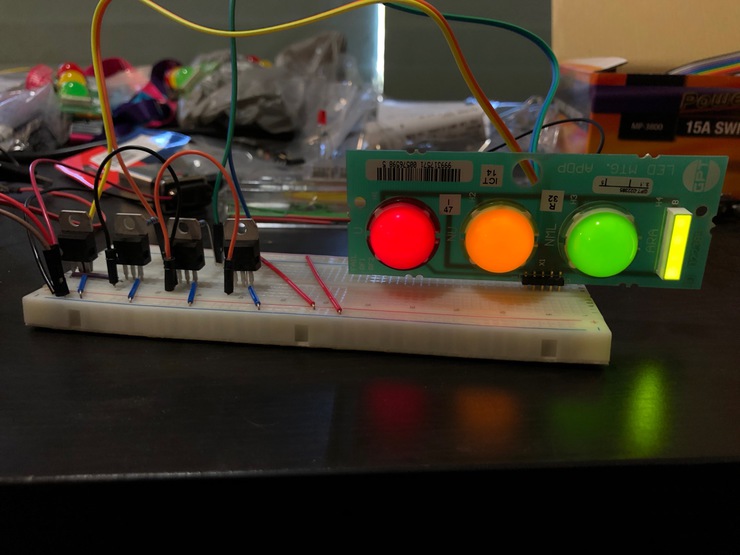
Working LED lights with BJTs acting as switches (not pictured: depleted 9V battery @ 5VDC, acting as base voltage; variable power supply @ ~20VDC
The Result
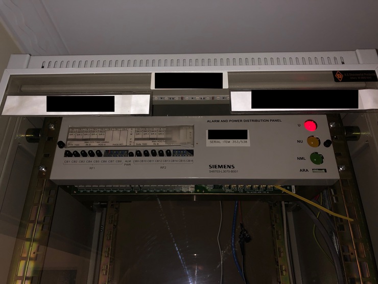
Working APDP with Urgent status
Everything operational
Now, whenever I have an IP connectivity outage, or a key server on my LAN goes down, I get an Urgent alarm (red LED showing). If my internal DNS server goes down, I get a Non-Urgent alarm. Otherwise, everything reports as Normal. With a error propagation time of ~15 seconds, I’m fairly happy that this can be used as a quick tool to tell if it’s just my computer that’s acting up, or indeed something has gone wonky on the network.